Script-generated LTE controller
A complete 4G mains lighting controller PCB, generated end-to-end from Python instead of drawn by hand.
A 220 VAC-powered lighting controller: four 16 A relay outputs, eight opto-isolated 220 V presence-sense inputs, an ESP32-S3 with native USB-C flashing, a SIMCom A7682E LTE Cat-1 modem and...
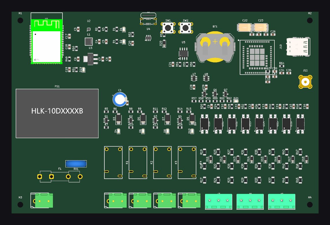
A 220 VAC-powered lighting controller: four 16 A relay outputs, eight opto-isolated 220 V presence-sense inputs, an ESP32-S3 with native USB-C flashing, a SIMCom A7682E LTE Cat-1 modem and a battery-backed DS3231 RTC on a 175 x 115 mm two-layer board.
The unusual part is the workflow: the whole KiCad 10 project (schematic, netlist, board, placement, zones) is produced by a home-grown Python generator (`tools/kigen.py`) that parses .kicad_sym libraries, embeds symbols, places instances on a 2.54 mm grid and wires every pin with global labels, then drives pcbnew, freerouting and kicad-cli for routing and fabrication outputs.
Built in a single day (2026-07-08) as a deliberately cheap, LCSC/JLCPCB-stockable design.
What it does
- 4x Hongfa HF32FV-16 16 A relay outputs with S8050 drivers, flyback diodes and status LEDs; pluggable 5.08 mm terminals with switched-L + N per channel
- 8x 220 VAC presence-sense inputs through LTV-817S optocouplers (3x100k series, 1N4148 anti-parallel, 47k/1 uF RC filter to bridge half-cycle gaps)
- Power tree: HLK-10M05 AC-DC (fused 5x20 T2A + 10D471K MOV) -> TLV62585 3 A buck for the 3.8 V modem rail with polymer bulk caps -> AMS1117 3.3 V logic rail
- ESP32-S3 with native USB-C (GCT USB4145 + USBLC6 ESD), BOOT/RESET buttons, WiFi/BLE as secondary connectivity
- LTE Cat-1 modem with micro-SIM, ESD arrays, SMA edge-mount antenna on a ~50 ohm coplanar trace, 1.8 V UART level shifting via SN74LVC1T45
- DS3231MZ TCXO RTC with CR2032 backup and alarm interrupt to GPIO
- Mains and logic zones physically separated with dedicated net classes (MAINS 2.5 mm/1.5 mm clearance, MAINS_SENSE, POWER, RF)
- Fully reproducible: edit generators, rerun chain (gen_sch -> ERC -> netlist -> gen_pcb -> DSN -> freerouting -> post_route -> export_all)
Wrote a from-scratch KiCad s-expression parser and schematic/board generator (~1.5k lines Python) that embeds library symbols, computes rotated pin endpoints and drives pcbnew placement and zone fill; ERC-clean generated schematic; mains-rated design rules; entire mixed mains/RF/USB/LTE board designed in one session. Unrouted at present - honest to call it a design study/generator demo rather than a fabricated board.
Want something like this?
I build it live on a Zoom call, you watch the screen, the timer stops when you say stop. First 15 minutes are free.